
Installation Waste Water Level Sensor Technical Bulletin
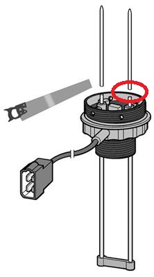
The N02-240-902 Waste Water sensor comes complete with a sealing kit. It also includes an and adapter plate to fit Vetus fresh water tanks. When fitting the sensor loosen the allen key screws holding the two capacitive rods in place. Fit sensor into tank until the correct depth is achieved, the two capacitive rods will shift upwards. This sensor can be adjusted to fit tanks from 60mm to 600mm depths. Leave a minimum of 10mm, maximum 15mm from lower edge of sensor to tank floor.
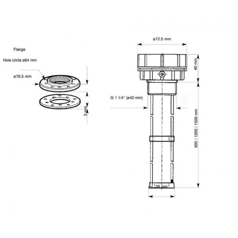
VERY IMPORTANT: When cutting the capacitive, push the rods thru to the required length and cut above the allen key screws, leave about 2-3mm. Cut rods using a wire or side cutter. DO NOT CUT THE RODS BELOW THE ALLEN KEY SCREWS, THIS WILL DAMAGE THE SENSOR. DO NOT REMOVE RODS!!
Now fit sensor to tank using the supplied sealing kit.
- Wiring
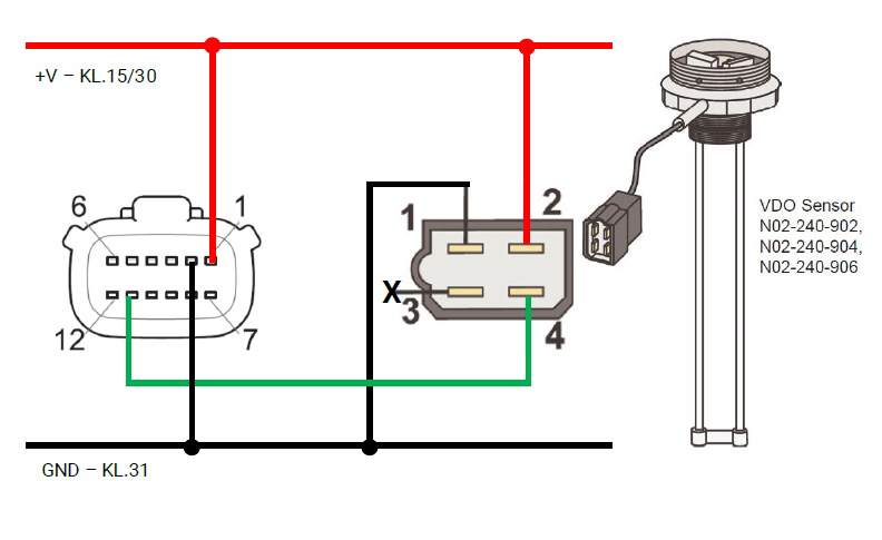
The N02-240-902 Sensor has a four pin plug fitted to it. You can remove this plug if you want too. You will be left with four wires, Brown, White, Yellow, Green.
- Brown = Signal Wire on Gauge
- White = External Warning - This wire can be connected to a buzzer or light to indicate when tank is at a certain level
- Yellow = Positive Power
- Green = Ground/Negative Power
- Calibration
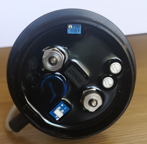
The Sensor must be calibrated for the full level (100%-20mA) by using the potentiometer:
- Fill tank to 100%
- Open the tank calibration process on the display to see real time current measurement.
- Turn the potentiometer until the value equals 20mA.
- If you have a capacitive manual VDO gauge fitted then once tank is 100% full turn the potentiometer until the gauge shows 100% or FULL.
- Alarm Range Setting
There are 2 adjustments that can be made under the cap for the external warning - white wire.
- P1 is the Low Alarm which ranges from 0% - 33%
- P2 is the High Alarm which ranges from 66% -100%
If you do not want to use the external alarm then adjust P1 to counterclockwise to a minimum value and adjust P2 clockwise to a maximum value.
Generally only P2 is used on a waste water tank so that an alarm is set off in the form of a light or a buzzer that tank is nearing full capacity. With external alarm connected fill the tank to the desired alarm signal capacity and turn P2 counterclockwise until the external buzzer or light comes on.
- Dip Switch Setting
You will find a dip switch located under the cap.
1= Connection to Ocean Line Indicator
0= Connection to Logic, Combi or EBD
Try both dip switch options until gauge shows a reading.
For any additional information please email info@dynamicelements.co.za